

Contents:
2. Scattering calculator – version 4.13
3. Mass-separator mode - version 4.12
5. Prefragment search - version 4.10
It is our pleasure to inform, that after long years of work the preprint of the paper on the LISE code has been submitted to Nuclear Instruments and Methods B: “The program LISE: a simulation of fragment separators”. The preprint of the LISE paper (Preprint NSCL MSU, MSUCL-1187, January 2001) is available as a pdf file (ftp://ftp.nscl.msu.edu/lise/documentation/lise.pdf, ftp://http:"//lise.nscl.msu.edu/lise.pdf).
ABSTRACT:
This paper is a description of the program LISE, which simulates the operation
of fragment separators, used in the production of radioactive beams via
fragmentation. The various aspects of the physical phenomena involved in
the production of such radioactive beams are discussed. They include fragmentation
cross sections, energy losses in materials, ionic charge state distributions,
as well as ion optics calculations and acceptance effects. Among the goals
of this program is a highly user-friendly environment, designed not only
to forecast intensities and purities for planning future experiments, but
also as a tuning tool during experiments where its results can be quickly
compared to on-line data. In addition, several general purpose tools such
as a physical parameters calculator, a database of nuclei properties, and
relativistic two body kinematics calculations make it also attractive in
experiments where radioactive beams are not involved. After a general description
of fragment separators, the principles underlying the calculations are
presented, followed by a practical description of the program and its many
features. Finally, a few examples of calculations are compared to on-line
data, both qualitatively and quantitatively.
2. Scattering calculator – version 4.13
Continuing the tradition of developing the program of physical calculators, in the new version the calculator of a scattering process was created. The access to this calculator is carried out through the menu: Calculation -> Scattering Calculator. The given calculator is a powerful and convenient tool for estimations of Coulomb scattering cross-sections, energies of scattered particles, both in the laboratory frame, and in the center-of-mass system. The calculator also allows to estimate the maximal scattered angle of particles in the laboratory frame, and also to estimate the rate of scattered particles in the detectors. The scattering angle can be input by one of four possible ways, picking thus the frame and scattered particle. The user can at once see the results of calculations for the given angle in the calculator (Fig.1), and also to construct the plots (Fig.2) Dependences of energies and angles in the laboratory frame on the scattering angle in the center-of-mass system are displayed: (qLAB = f(qCM) and EnergyLAB = f(qCM), and also plots q 4LAB = f(q 3LAB) and EnergyLAB = f(qLAB). Also the user can construct the plots of cross-sections of Coulomb scattering, both in the center-of-mass system, and in the laboratory frame (Fig.3).
In a series of cases for one scattering angle in the laboratory frame there can correspond two scattering angles in the center-of-mass system (as for example, for 6He on Fig.2). In such cases the user should set a direction of searching of the relevant angle in the center-of-mass system, if the initial angle is input in laboratory system.
In the basis of the calculator lie the relativistic evaluations. The user can be convinced of it in case of the scattering of two identical particles at small energies (about some MeV per a nucleon) and at higher energies.


Fig.1. Calculations made by the Scattering calculator for 6He (25AMeV) on hydrogen at an angle of 140 degrees in the center-of-mass system for the ground state 6He (upper figure) and in case of excitation of the 1.8 MeV state (bottom figure).


Fig.2. Angular and energy dependences for the scattering of 6He (25AMeV) on hydrogen for the ground state 6He (upper figure) and in the case of excitation of the 1.8 MeV state (bottom figure).

Fig.3. Differential cross-sections of Coulomb scattering of 40Ar (46.7AMeV) +Ni in various frames.
In the calculations it is supposed, that the beam particle undergoes scattering in the middle of a target in view of losses of energy in the first half of the target. Further on, before registration in the detector both particles also lose kinetic energy in the target of width t/2/cos(qLAB),, where t is the thickness of the target. The target is considered homogeneous so sa to avoid complicated calculations with a composite target.
One convenience is also the opportunity of the assignment of excitation in one of the scattered particles. So on Fig.1 and Fig.2 the examples of scattering for the reaction 6He(25AMeV) + H without excitation 6He and for excitation 6He to 1.8 MeV are given (it is certainly supposed, that the nucleus does not collapse, though we know, that 6He is unstable at excitation of a level 2+).
Also the given calculator can be used for estimating the intensity of the primary beam falling on the detector for registration of scattered particles, that very often is applied in physical experiments for monitoring the beam.
In the new version of the program in case of calculations of kinematics
of a two-body reaction (menu Utilities -> Reaction's kinematics /two
body/) the user will receive two additional plots q
4LAB = f(q 3LAB) and EnergyLAB
=
f(qLAB).
3. Mass-separator mode - version 4.12
3.1 Cutout of the second dipole

Fig.4. The button of insert / lockout of the second part of a spectrometer.
Initially the program LISE was made for model operation of spectrometers consisting of two dipoles. Further the Wien filter of velocities, and later one dipole behind the filter permitting to yield a classification by A/Q was supplemented as an option. However, during operation with the program was clarified, that more prime configuration of operation in a mode of a mass separator consisting of one of a dipole is not realized, that makes possible to simulate experiments on such installations as SPEG, S800, MSP-144 and so on. Certainly, it was possible to accept an optical matrix of the second part of a spectrometer for single and to increase acceptances of the second part of a spectrometer, and also to increase slots in a final focal plane, so that there were no losses in transmission in the second part of a spectrometer. However, all this causes inconveniences, owing to what by more prime expedient it was embodied in the program. Now the user can switch off (Fig.4) the second dipole (accordingly to exclude from the program all calculations, connected to a wedge).

Fig.5. Dialogue “Optics” in the mass-separator mode
Switching off the second part of the spectrometer reduces the optical matrix of the second part of the spectrometer to identity matrix (see A on Fig.5), and the acceptances of the second part of the spectrometer are disregarded (see Fig.6). After lockout of the second part of the spectrometer, the user is notified, that the configuration of the program was automatically changed. At repeated insert of the second part of the spectrometer there is again a message, that the user should tune the second part of the spectrometer by hand or load it from the configuration file.

Fig.6. Dialogue “Acceptances and Slits” in the mass-separator mode
3.2 New dE-X plot in the dispersive focal plane
 The dE-X
plot in the dispersive focal plane is the most important one for experiments
on mass separators.For this reason it was created in the new version of
the program by adding it to already the existing dE-X plot in the final
focal plane. In the program already there was an one-dimensional plot of
horizontal distribution of fragments (X-Brho selection plot in IDFP). To
obtain the plot of total kinetic energy versus X it is necessary first
to enter major enough thickness of the detector for a stopping in him of
products of reaction.
In Fig.7 the dependence of energy losses of the isotopes of nitrogen in the third detector on the horizontal position in the focal plane of the magnetic spectrograph MSP-144 [Bel98] in the reaction 12C(190MeV) + B is shown. In this case the focal detector was an the ionization chamber [Bel89] with 4 segmented anodes. The pressure of the gas is selected so that the studied ions are stopped in the third detector. In the figure it is well visible, that at small energies the ions of nitrogen do not reach the 3-rd detector and are stopped in the second detector, which corresponds to the left-hand part of the spectrum. At higher energy, that corresponds to the right part of the diagram, the ions fly further than the third detector. Two vertical lines in the figure denote the size of the detector (-95 ¸ 95 mm).
The configuration file of the magnetic spectrograph MSP-144 has been incorporated in the list of LISE’s setups.
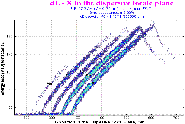
Fig.7. The LISE code simulation: Two-dimensional plot of ER vs. X for the 12C(11B,13N)10Be reaction at 190 MeV incident energy. For details see the text.

Fig.8. Comparison of experimental (upper) and calculated (lower) distributions. See the text for details
In Fig.8 the comparison of experimental distributions [Bel98] with calculated ones by the program LISE for the reaction 12C(190MeV) +B is presented. The upper plots represent experimental spectra D E2 vs. ER and ER vs. X, where ER is the rest energy, given by the third detector. On the lower pannels the calculations accordingly represented. Inferior two-dimensional plot of X vs. ER there is a fragment of Fig.7 that corresponds to a working band of the focal detector.
3.3 New opportunity to select the velocity of reaction products
The new version of the program to be used for a mass separator gives the opportunity to select the velocity of the reaction products in the two body relativistic kinematics (Fig.9-A). In the given evaluations the angle (Fig.9-B) of the mass separator with respect to the beam direction is included. This was made so as to be able to simulate results not only for fragmentation reactions, as was included earlier in the program, but also for transfer reactions. It is a first step in the program for this type of reaction, but as shown in chapter 3.5. it is still necessary to work in this direction.
In Fig.10 the distributions of velocities of reaction products from mass of an ion and from particle energy represented, where the calculations with evaluation, new to the program, of velocity of reaction products – two-body kinematics already represented.

Fig.9. Dialogue “Production mechanism – Fragment
velocity”

Fig.10. The distributions of velocities of reaction products from mass of an ion and from particle energy
3.4. New image of the dialogue “Beam”
In the version the user can set the beam intensity not only in electrical nanoAmpers (enA), in kilowatts and particles per one second (pps), but also in the well-known format of particles nanoAmpers (pnA) (see Fig.11-B). Also user at input of energy of a beam automatically can supervise its total kinetic energy (Fig.11-A).

Fig.11. Dialogue “Beam”
3.5. It is still necessary to work on:
2. Angular distributions of transfer reactions;
3. Width of momentum distributions of transfer reactions;
4. Energy dependence of reaction products on angle for first four choices of velocity;
5. Addition of some more invariance utilities for operation with MSP-144;
6. Parameterization of density of butane from pressure.
 Definition
of the fragment outputs is a rather labour-consuming process: it is necessary
to handle tens of matrixes, each carring the information on several tens
of ions. For example, in the experiment on a beam 112Sn [Lew94]
the nuclei with mass number from 8 up to 53 were identified. For each value
of the magnetic rigidity there were four matrixes for various charge states
of the reaction products, and in everyone more than five hundred ions.
After measuring all data are imported to the computer for further analysis.
The volume of operation can roughly be estimated:
500 ions ´ 4 matrixes for a charge state ´ 10 values of the magnetic rigidity = 20 000 values!
It is necessary also to mark the high probability of subjective errors of the experimenter, connected, both with the analysis of two-dimensional peaks, and with the transport of the information to the computer. In this connection, for the automized searching of two-dimensional peaks and definition of statistical parameters the “Bi” program was created.
There are three versions of the program:
|
|
|
|
|
|
|
|
|
|
|
ftp://dnr80.jinr.ru/bi |
|
|
/format “ SURFER / |
|
(in-built in LISE code) |
|
|
GANIL Acquisition after FTP ASCII files |
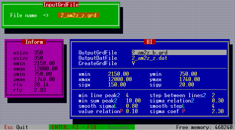
Fig.12. The interface window of the “Bi” program (version under MS DOS), intended for the automized searching of two-dimensional peaks and definition of statistical parameters.
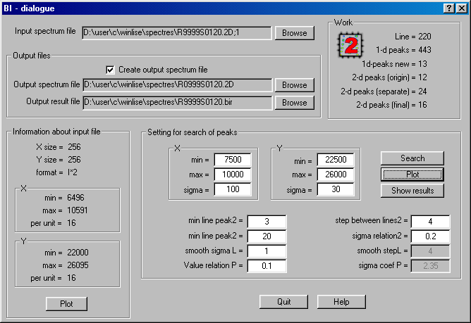
Fig.13. The dialogue “Bi”
in LISE code.
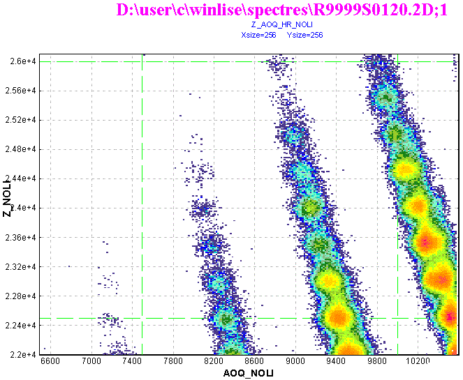
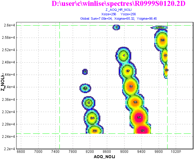
Fig.14. The experimental spectrum is shown in the left figure and in the right figure accordingly the spectrum obtained after searching and definition of parameters of two-dimensional peaks in the selected rectangle by the "Bi" subroutine in “LISE” code.
The examples of operation of the program are presented in Fig.12,13. All versions produce the results of the analysis (see Fig.14 and Fig.17) in a pictorial view (new spectrum of the same format) and as a table (Fig.15) with all statistical parameters of all the identified peaks. The program can be modified to other spectra formats easily without changing of its basis of a spectrum by adding the relevant subprograms of reading and recording spectra. In order to be able to switch on the new format of a spectrum it is necessary to senda request to the authors of the program with a description of structure of the spectra (desirablya code source), and also as an example an experimental spectrum in this format. It is also planned to make code conversion of spectra of one format in to another.
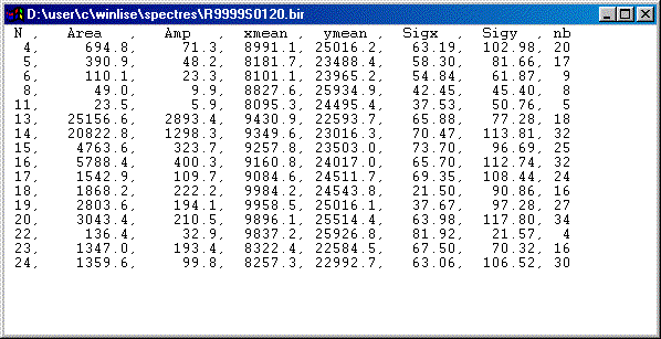
Fig.15. Window with a text file with the results of searching of two-dimensional peaks in the spectrum represented in Fig.14 by the “BI” subroutine in the “LISE” program.
The algorithm of operation of the program of the automized searching of two-dimensional peaks and definitions of their statistical parameters is presented in a Fig.16. The input of initial model of searching consists in the following:
 ,
,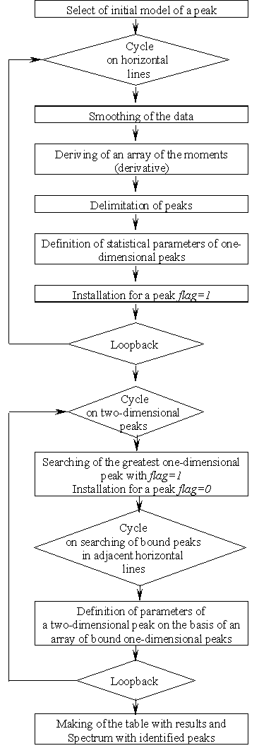 |
Fig.16. Algorithm of operation
of the program of the automized searching of two-dimensional peaks and
definitions of their statistical parameters.
Fig.17. In the upper figure the experimental spectrum of yields with Z=45-53 in the reaction 112Sn (58AMeV)+Ni [Lew94] for completely stripped nuclei (Q=Z) at magnetic rigidity Br=1.98835 Tm depending on the mass number Z and the quantity A/Q. In the low panel the spectrum obtained after searching and definition of the parameters of two-dimensional peaks by the "Bi" program (VMS-version) is given. |
The most important moment of the program is searching an one-dimensional peak and definition of its boundaries, under condition of, that this searching was prompt enough and effective. Originally searching was realized with the help of an evaluation derivative in each point. Radiating from extremes:


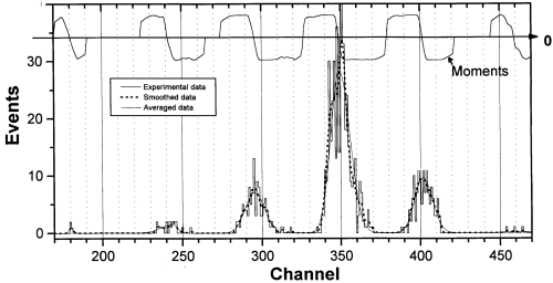 |
Fig.18. Results of smoothing of experimental data and definition of their "moments" for an one-dimensional spectrum. |
The stayed interior parameters of the program (according to the menu in a Fig. 1) have the following functions:
For the first time in the program concept the prefragment was input for argument of a discrepancy of experimental values of fragments velocity and formula, calculated with the help formula [Ram85], where it is supposed, that kinetic energy leaves on a difference of surface energies between a fragment at the moment of interaction with a target and its ground state in the guess of the spherical shape. However calculated values were underestimated, that is why it was supposed, that is necessary to calculate velocity of a prefragment, guessing then its equal velocity of a fragment.
In further concept of a prefragment also was entered for calculations of momentum distribution width on [Fri83]. The user in all above-stated cases had the right of a select: to use concept of a prefragment whether or not.
However by more essential usage of calculations of a prefragment was by introduction in the program of a universal parameterization of fragment momentum distribution. Moreover concept of a prefragment underlies this parameterization. In this connection in the new version the dialogue Prefragment has appeared Fig.19, where the user can set some methods of searching of a prefragment and see the results of calculations of a prefragment.
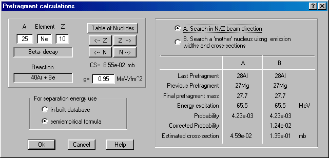
Fig.19. Dialogue “Prefragment calculations”.
The basic algorithm consists in the following:
|
|
maximum Ãn(27Ne) CS(27Ne), Ãp(27Na) CS(27Na), Ãa(30Mg)
CS(30Mg)
Fig.20. Two possible methods to search of a prefragment. |
5.1. Attempt to extrapolate cross-sections of exotic nuclei
The probability of formation of a final fragment from the retrieved fragment automatically pays off by searching a prefragment. Using this quantity and the cross-section of a prefragment production from the parameterization EPAX, it is possible to estimate a production cross-section of a final fragment. It is especially interesting for nuclei far from the stability line. As it was already mentioned, the basic disadvantage is that the experimental cross-sections are used.
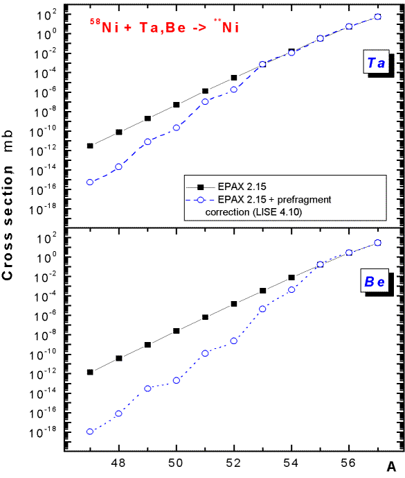
Fig.21. Cross-sections for production of Ni-isotopes with a 58Ni beam on a Ta-target (upper picture) and a Be-target (bottom picture). Black solid rectangles correspond to cross-sections calculated by EPAX 2.15, open blue circles the previous cross-sections with prefragment corrections.
In various experiments devoted to the study of the properties of exotic nuclei, it was marked, that the greatest output of reaction products is reached on heavy targets, though the programs, including the given program, predict on the basis of the parameterization EPAX a greater output in the case of light targets. First of all it is possible to explain this by the fact that in the given parameterization the relation between cross-sections for various nuclei is always constant, that does not correspond to the reality. So in experiments on the synthesis of 48Ni with a beam 58Ni [Bla00] the advantage of a nickel target compared to a carbon target was supervised, in experiments on study of the stability of 28O [Tar97] the greatest output for nuclei in the region N=20 is shown. So in experiments on the synthesis of 100Sn [Lew94] the greater output in the case of a Ni-target was explained by the experimenters by the additional contribution from transfer reactions. Also it was marked, that experimental cross-sections for superexotic nuclei are much below the calculated ones.
However, it is possible to explain this by the greater excitation energy of prefragments in the case of light targets, due to the fact that the prefragment has longer chain of daughter nuclei, which leads on to a more stable final nucleus. On the basis of the new model of calculations of a prefragment the attempt was made to estimate cross-sections for the case of proton-rich isotopes of nickel produced with a beam of 58Ni (see Fig.21). As it was already mentioned, the basic disadvantage is that the cross-sections used for these estimations also are experimental. For the given calculations the searching of a fragment was done by the N/Z method, and the characteristics of nuclei were calculated using the formula, instead of being taken from the database (see Fig.19). From Fig.21 it is visible, that in order to produce the isotope 49Ni the ratio between the original parameterization EPAX and calculations with prefragment corrections for a Ta-target constitutes 260, whereas for Be-target this value already is more than 4000, which then explains the advantage of heavier targets.
5.2. Calculation of isotope characteristics with the semi empirical formula.
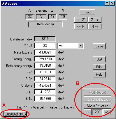
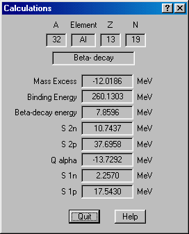
In this version of the program the user has got an opportunity to add the data on new isotopes. The insertion of a new record is possible if the user inserts in the dialogue an isotope, which does not exist in the database. Pressing on the key "Add record" (Fig.22) the user creates a new record, and the database automatically remakes indexation. Also the user can get calculated values for the given isotope (button “Calculate”) on the basis of the semi empirical formula (Fig.23). For those evaluations, where usage of the characteristics from the database is required, but the data on this isotope is missed in the database, the program calculates them on the basis of the semi empirical formula.
 |
 |
|
|
|
[Bel89] A.V.Belozyorov et al., Report P15-89-2255, JINR, Dubna, 1989.
[Bel98] A.V.Belozyorov et al., NIM A 411 (1998) 343-350.
[Lew94] M.Lewitowicz et al., Phys. Lett. B 332 (1994) 20-24.
[Ram85] F.Rami et al., Nucl.Phys. A444 (1985) 325.
[Fri83] W.A.Friedman, Phys.Rev. C27(1983) 569.
[Gai91] J.-J.Gaimard, K.-H.Schmidt, Nucl.Phys. A531 (1991) 709-745.
[Bla00] B.Blank et al, Phys.Rev.Lett. 84 (2000) 1116-1119.
[Tar97] J.-J.Gaimard, K.-H.Schmidt, Phys.Lett. B409 (1997) 64-70.